Mario.Tapilouw

Wednesday, April 11, 2012

Automatic Threshold

Threshold plays an important role in image segmentation. The threshold value in an image can be manually or automatically set. Manual threshold is not always suitable for all situation because different image may have different intensity distribution.

There are some developed automatic threshold algorithm that have been developed. In this article we are going to use the triangle algorithm, one of the simplest method that I know. It's quite old but still effective to be used under certain image conditions. The one we are going to write here is a slightly modified version from the one written in this reference:

Zack GW, Rogers WE, Latt SA (1977), "Automatic measurement of sister chromatid exchange frequency", J. Histochem. Cytochem. 25 (7): 741–53, PMID 70454

In order to follow these steps, we need to set up our compiler, in this example I use Visual Studio 2008 and OpenCV 2.1.

Ok, let's get our hands dirty, just make sure that OpenCV has been setup properly in your system:
1. Declare some IplImage objects:

 IplImage* image(0);     
IplImage* imageGrey(0);
IplImage* imageBin(0);

2. Load the image from a file:
 image     = cvLoadImage((char*)(void*)Marshal::StringToHGlobalAnsi(openFileDialog1->FileName), 1);    
imageGrey = cvCreateImage(cvSize(image->width, image->height), 8, 1); imageBin = cvCreateImage(cvSize(image->width, image->height), 8, 1);

3. Convert the color image into grayscale image, we're going to perform the threshold in grayscale value. We can also perform threshold for all the channels afterwards.

cvCvtColor(image, imageGrey, CV_BGR2GRAY );

4. Create the histogram of the image, there's a trick in histogram calculation here, hope you understand the trick:

int histogramGrey[256] = {0};
for(int row=0;rowheight;row++)
{
for(int col=0;colwidth;col++)
{
CvScalar m, n;
m = cvGet2D(imageGrey, row, col);
histogramGrey[(int)m.val[0]]++;
}
}

5. There's an assumption in this algorithm, the background and the foreground must be separated, so we're going to find out the peak of the background and the foreground. The simplest way is to calculate the center of mass of the histogram and find the peak in each region (left a nd right).

float Iz = 0;
float I = 0;
float peak = 0;

for(int i=0;i<256;i++)
{
Iz += (i * histogramGrey[i]);
I += histogramGrey[i];
}

peak = Iz / I;
6. Then the next step is to find the left peak (background) and the right peak (foreground). A simple peak search will do.

// finding the left peak
for(int i=0;i<(int)peak;i++)
{
if(peakL < histogramGrey[i])
{
peakL = i;
}
}
//finding the right peak
for(int j=(int)peak;j<256;j++)
{
if(peakR < histogramGrey[j])
{
peakR = j;
}
}
7. Ok, now we have a line con necting the left and the right peak. Then the next thing to do is to find a point in the histogram with the maximum distance from t he line. The code is a little bit dirty with typecasting but it works.
for(int i=peakL+dist;i<peakR-dist;i++)
{
float distance = (((peakR - peakL)*(histogramGrey[peakL] - histogramGrey[i])) - ((peakL - i)*(histogramGrey[peakR] - histogramGrey[peakL])) )/
sqrt( ((float)peakR - (float)peakL) * ((float)peakR - (float)peakL) + (((float)histogramGrey[peakR] - (float)histogramGrey[peakL]) * ((float)histogramGrey[peakR] - (float)histogramGrey[peakL])));

if(minDist > distance)
{
autoThresholdVal = i;
}
}
8. Finally we got the threshold valu e and then we can call cvThreshold() function.

cvThreshold( imageGrey, imageBin, autoThresholdVal, 255, CV_THRESH_BINARY );

With a little modification, the algorithm can be implemented real time by adding it into the webcam callback.

Et Voila! Here is the screen shot of the result. The left image is the live image from a webcam and the right image is the image after performing auto threshold.

Hope it's useful!

Labels: , , , ,

Thursday, December 08, 2011

Multiple Webcam using OpenCV 2.1 and Visual Studio 2008

I just found out that it is not difficult to connect to two webcam using OpenCV and do image processing on the captured images. I used OpenCV 2.1 and Visual C++ 2008 for this program, so those who are familiar with Visual C++ 2008 should be familiar with this code. The installation and configuration of OpenCV is explained clearly in their wiki and you can follow the steps written there.

We need to create two capture objects, one for each camera:

CvCapture* capture;
CvCapture* capture2;

Also, create two IplImage objects for the two cameras:
IplImage* image;
IplImage* image2;

The CvCapture and IplImage objects have to be initialized before use, add a button to your form and add these initialization lines:
int w = 640;
int h = 480;

// creating the capture fwom webcam #1
capture = cvCreateCameraCapture(0);
capture2 = cvCreateCameraCapture(1);

// parameter setting
cvSetCaptureProperty(capture, CV_CAP_PROP_FRAME_WIDTH, w);
cvSetCaptureProperty(capture, CV_CAP_PROP_FRAME_HEIGHT, h);

cvSetCaptureProperty(capture2, CV_CAP_PROP_FRAME_WIDTH, w);
cvSetCaptureProperty(capture2, CV_CAP_PROP_FRAME_HEIGHT, h);

// initialization of iplimage object
image = cvCreateImage(cvSize(w, h), IPL_DEPTH_8U, 3);
image2 = cvCreateImage(cvSize(w, h), IPL_DEPTH_8U, 3);

Then the next thing is to declare a function for capturing the images:
private: System::Void ProcessFrame(System::Object^ sender, System::EventArgs^ e)
{ // query the frame and capture
image = cvQueryFrame(capture);
image2 = cvQueryFrame(capture2);

cvShowImage("camera 1", image);
cvShowImage("camera 2", image2);

if(blnGrabImage)
{
cvSaveImage("image_left.bmp", image);
cvSaveImage("image_right.bmp", image2);
blnGrabImage = false;
}
}

We have to register this function to be called by the system, add these lines after the initialization of the capture and the images:
Application::Idle += gcnew EventHandler(this, &OpenCVImage::Form1::ProcessFrame);

There are two important parts in this line, the first one is
Application::Idle += gcnew EventHandler
which tell the system to add an event handler to the system when the system is idle and the other thing is this part:
&OpenCVImage::Form1::ProcessFrame
which tells the system to call this function every time there's a new event in the system, in this case OpenCVImage is the name of the project, Form1 is the name of the Form, and ProcessFrame is the function that is going to be called.

So, that's it, tidy up the code a little bit and ready to run. If you're successful you'll get something like this:
1. For single camera:
2. For multiple cameras:
- left camera:
- right camera:
Left and right are seen from the objects' viewpoint facing the camera...

Good luck!

Labels: , , , ,

Monday, May 09, 2011

Plane Fitting using OpenCV


As what I've promised, I'm going to write about plane fitting using OpenCV. It's quite straight away and quite similar to my previous post, the difference is only about the physical representation of the variables in the equations. This time it's only a plane fitting, so it's a linear least square fitting. Later I would like to explore non-linear fitting as well and share it here when I have made it.

Let's say that we have a set of data that represents a plane in 3D coordinate X-Y-Z and modeled as Axi + Byi + C = zi. where i is the enumerator of the data (0~n).

Using the same approach, we can use matrix to represent the simultaneous equation and solve it.I will directly show you how.
1. prepare the matrices for the data.
CvMat *res  = cvCreateMat(3, 1, CV_32FC1);
CvMat *matX = cvCreateMat(10000, 3, CV_32FC1);
CvMat *matZ = cvCreateMat(10000, 1, CV_32FC1);
2. input the data into the matrices.
for(int row=0;row<100;row++)
{
for(int col=0;col<100;col++)
{
int idx = row * col;
double val = cvmGet(filteredMat, row, col);

cvmSet(matX, idx, 0, col*pixScale);
cvmSet(matX, idx, 1, row*pixScale);
cvmSet(matX, idx, 2, 1);
cvmSet(matZ, idx, 0, val);
}
}
3. solve the equation
cvSolve(matX, matZ, res, CV_SVD);
A = cvmGet(res, 0, 0);
B = cvmGet(res, 1, 0);
C = cvmGet(res, 2, 0);

4. calculate the distance between the plane and the real data.


double sqrtc = sqrt(pow(A, 2) + pow(B, 2) + pow(C, 2));

float min = 100;
float max = -100;

// plane generation, Z = Ax + By + C
// distance calculation d = Ax + By - z + C / sqrt(A^2 + B^2 + C^2)
// pointlist generation
for(int row=0;row<filteredMat->rows;row++)
{
for(int col=0;col<filteredMat->cols;col++)
{
double Zval = cvmGet(filteredMat, row, col);
double val = col*pixScale*A + row*pixScale*B - Zval + C;
double distance = val / sqrtc;

if(min > distance)
min = distance;

if(max < distance)
max = distance;

cvmSet(planeMat, row, col, distance);
}
}
Here is an example of this plane fitting, this is the surface before fitting, this is measurement result of a flat surface using white light interferometry:
and after fitting the result is:
The color represents the height, so we can see that after fitting the color of the surface is almost the same only a small variation of the surface. The sample should be flat and smooth, however it's not smooth anymore due to wear. However, the real scale is nanometer, the variation that we see in the result is around 100 nm.

Labels: , , , ,

Thursday, April 08, 2010

Configuring OpenCV Library in Microsoft Visual Studio Environment

I have a plan to change my compiler to Visual Studio because I want to use OpenMP in the near future. However, my dream is to write machine vision algorithm that is platform-dependent, it can work with any image grabbing cards, any camera and runs at any OSs (this one might not too important for now).

Although many programmers have posted these tips, I still want to post this kind of information so that when I need to re-configure my Visual Studio I can find these steps easily, from my own blog.

First thing you need to do is go to the project setting:
We need to tell Visual Studio which directory to the include files of OpenCV, we can do this by choosing the "Additional Include Directories"

Then, choose the General part of Linker tab in the Project settings and add the additional library directory:
Then the last step is to add the additional dependency on the Input part of Linker tab and add these values.

Then, to test whether this this settings is correct or not, you can create a simple project like this:

#include
#include
#include

int main(int argc, char ** argv)
{
const char* filename = argc >=2 ? argv[1] : "C:\\Users\\mario\\Desktop\\vc++\\testsaveimage\\debug\\1.JPG";
IplImage * im;

im = cvLoadImage( filename, CV_LOAD_IMAGE_GRAYSCALE );
if( !im )
return -1;

cvNamedWindow("win", 0); cvShowImage("win", im);
}

Try to build this project and see whether you have an error message or not.

Good luck.

Labels: , ,

Friday, April 02, 2010

Copying Euresys EImage into OpenCV IplImage

I tried to find a way to copy Euresys' EImage to OpenCV's IplImage. The reason is that I want to develop my algorithm based on the free OpenCV library so that I can try it anytime in my laptop without having to attach Euresys cards or license key.

Another advantage of doing this is that when I change to another image grabber card, I can still use my algorithm with some data conversion process. Speeding up will be a further issue after the algorithm is proven to work correctly.

So, here it is, by using this piece of code you can copy the EImage data seamlessly into IplImage.

Suppose that we have these objects:
IplImage *GLCVImage;
EImageBW8 GLImage;

We can copy the data directly by passing the pointer;

GLCVImage->imageData = reinterpret_cast < char* >(GLImage.GetImagePtr());


Hope it works with yours. I use this quite often and I post this here to make it easier for me in case I need to do the same thing again.

Labels: , , ,

Wednesday, March 31, 2010

Real Time 1D FFT

Another project using FFT, this time I need to have a 1-D FFT transform for analyzing frequency component of a signal. I have an idea to do this FFT real time and show it using my previous technique for GUI using openCV.

I found the reference for making 1D FFT from this website and I modified the source code to work with my compiler and highgui library from OpenCV for showing the result.

For the data buffer, I created a circular buffer using std::deque, continuously updating the buffer using timer and show it into the screen. Currently my FFT class needs an array as the input, so there's an overhead for converting the std::deque to array, so I'm planning to modify my source code for handling std::deque directly for saving processing time.

The data is generated by using a TTimer (not really accurate though.. :( ) and it is sampled by another TTimer. I am planning to move to multimedia timer instead because it is faster and more accurate. The screenshot of the output from this circular buffer is as follow:

And the output of the frequency spectrum is as follow:

The sampling frequency is 250 Hz and the signal source is 50Hz. I am going to use multimedia timer instead for faster sampling time. One thing that I found is that the update rate of my real time viewer is limited to several milliseconds (2-3 ms).

The detail of the FFT source code can be found in this website so I won't post it here and also you can read the "Numerical Recipes in C" book which is quite a good book for programmers.

Labels: , , ,

Monday, March 29, 2010

Real Time FFT using OpenCV

Recently I tried to combine Fast Fourier Transform with my previous webcam project with OpenCV. I use cvDFT() function to generate forward FFT of the image.

The result is surprising, it's quite fast. I tried using my Logitech Quickcam and I can generate the FFT of the image in real time. I will post the details later because I combined it from several sources and had to do some modification to make it run real time without having memory leak issues.

Here's a screenshot:

Another screenshot with a sine grating as the object. If you understand how 2D FFT works, you might have an idea whether this is correct or not.

My webcam runs 15fps and the size of the image is 320x240. I'm going for a faster and larger camera, and doing IFFT, just wait and see, hehehe... :D

Actually this is not directly related to my job, I did this mainly for fun and curiosity :D.

Labels: , , ,

Wednesday, November 11, 2009

Having fun with a webcam (part 2)

These two days I introduced OpenCV to some students in my Lab. I realized that it's not an easy task to introduce a new library to the students. I did try my best, but I found out that only some students understand how to use it (I hope I'm wrong :)).

Nothing is instant when you learn something. Everything needs a process, it took more than a year for me to understand how OpenCV really works and how I can take advantage of it.

Recently, I'm playing with image acquisition using webcam. It's fun for me becaue I can test my algorithm before I connect it directly to the real camera in my Lab. Here are some images I got from my tutorial class yesterday and today, grabbed from the webcam.


Labels: , , ,

Monday, October 26, 2009

Camera Calibration using OpenCV

Actually this is one of the thing that I wanted to try last two year but at that time I didn't understand how to use it so I left it. But right now I have understood how to use this, so I would like to share it with you.

The usage is very simple. If you have already succeeded with capturing webcam using OpenCV, this example will be a lot more fun than that :D.

Suppose you have already connect your webcam to be captured using OpenCV, what you need to do is preparing these variables:

int patternCol(7);
int patternRow(4);
int numOfCorner(28);
int cornerCount(0);
int nBoards(8);
int successes(0);
int step(0);
CvPoint2D32f *cornerPoints;

Remember that you need to initialize the cornerPoints using new because it's a dynamic array.

Then, you need to add these lines into the callback of your webcam, suppose the variable of your callback is image:

int found = cvFindChessboardCorners(image, boardSize, cornerPoints, &cornerCount, CV_CALIB_CB_ADAPTIVE_THRESH);
cvDrawChessboardCorners(image, boardSize, cornerPoints, numOfCorner, found);

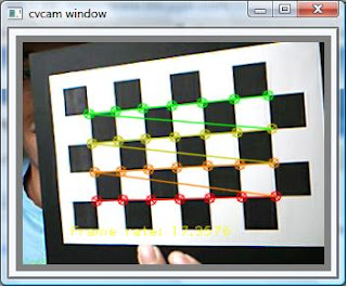
What you will see is that the chessboard corners are marked with a circle. If the circle has different colors, then it means the algorithm is successful. Something like this:

Then, the next thing you have to do is to save the position of the corners into a variable until you have enough images to perform the camera calibration. I tried using only 8 images, you can try more. I set the number of images using nBoards variable.

if( cornerCount == numOfCorner )
{
for( int i=step, j=0; j <>
{
CV_MAT_ELEM( *image_points, float, i, 0 ) = cornerPoints[j].x;
CV_MAT_ELEM( *image_points, float, i, 1 ) = cornerPoints[j].y;
CV_MAT_ELEM( *object_points, float, i, 0 ) = j/patternCol;
CV_MAT_ELEM( *object_points, float, i, 1 ) = j%patternRow;
CV_MAT_ELEM( *object_points, float, i, 2 ) = 0.0f;
}
CV_MAT_ELEM( *point_counts, int, successes, 0 ) = nBoards;
successes++;
}

Then, the next thing is to calibrate the camera using these lines of code:
CvMat* object_points2 = cvCreateMat( successes*nBoards, 3, CV_32FC1 );
CvMat* image_points2 = cvCreateMat( successes*nBoards, 2, CV_32FC1 );
CvMat* point_counts2 = cvCreateMat( successes, 1, CV_32SC1 );

// Transfer the points into the correct size matrices
for( int i = 0; i <>
{
CV_MAT_ELEM( *image_points2, float, i, 0) = CV_MAT_ELEM( *image_points, float, i, 0 );
CV_MAT_ELEM( *image_points2, float, i, 1) = CV_MAT_ELEM( *image_points, float, i, 1 );
CV_MAT_ELEM( *object_points2, float, i, 0) = CV_MAT_ELEM( *object_points, float, i, 0 );
CV_MAT_ELEM( *object_points2, float, i, 1) = CV_MAT_ELEM( *object_points, float, i, 1 );
CV_MAT_ELEM( *object_points2, float, i, 2) = CV_MAT_ELEM( *object_points, float, i, 2 );
}

for( int i=0; i <>
{
CV_MAT_ELEM( *point_counts2, int, i, 0 ) = CV_MAT_ELEM( *point_counts, int, i, 0 );
}

// At this point we have all the chessboard corners we need
// Initiliazie the intrinsic matrix such that the two focal lengths
// have a ratio of 1.0

CV_MAT_ELEM( *intrinsic_matrix, float, 0, 0 ) = 1.0;
CV_MAT_ELEM( *intrinsic_matrix, float, 1, 1 ) = 1.0;

// Calibrate the camera
cvCalibrateCamera2( object_points2, image_points2, point_counts2, cvSize( image->width, image->height ),intrinsic_matrix, distortion_coeffs, NULL, NULL, CV_CALIB_FIX_ASPECT_RATIO );

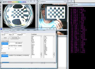
the output of the calibration is these two matrices: intrinsic_matrix, distortion_coeffs. You can save it into a file using cvSave(...) or directly call it from somewhere in your program.

These are some excerpts of the steps that I implement in my program. I followed the examples provided in Chapter 11 of OpenCV book :). If you're interested just try it :D


Wait for my next post about why this camera calibration stuff is important, hehehe... :D

Labels: , , , , ,

Wednesday, October 07, 2009

Real time Lissajous Graph using OpenCV

If you need a real time charting tools, you might need to make one by your own. In my case, I need to observe the Lissajous Curve of my signal to ensure the phase difference between two signal is correct.


We could perform this using oscilloscope if it is electrical signal, but in my case I need to do take the data from an image captured by camera and I need to observe the Lissajous figure at real time. I found that common windows GUI component (at least the one that I use..) is not fast enough. So I create a custom graph using OpenCV which cost me around 2-3ms to show.

I like OpenCV because it's fast and it's enough for my application. For example if we have a signal like this one and we want to check the phase difference between the Blue point and the Red point, or you want to check the phase difference between Red point and Yellow Point. First we have to determine the points.


We can draw it on a Lissajous Curve by drawing the intensity on the X-Y axis as follow. This is simply just drawing a point based on the intensity of the point.


Based on the theory, if the phase difference is 90 degree, the Lissajous curve will be a circle. We can apply circle eccentricity algorithm to determine whether it's a circle or not. In my case, I haven't implemented it yet. If the shape is almost circle, then it is just enough for my application.

Labels: , , ,

Thursday, October 01, 2009

Creating a custom report based on OpenCV

If you need to create a colorful chart with simple text information, this article might be useful for you. In my case, I need to develop a software for measuring an object and usually if the result is visualized using Matlab. Hmm.. it takes time and usually what we need might be only a simple result.

I want to do this because sometimes when I need to present a data, I still have to set the fonts size and some other settings in order to get several results with the same style and when I use different computer, the size and the resolution of the image changes, and it takes a long time just to set the image properties. Such a boring task...

So, I came up with an idea to visualize the data using our own software. Therefore, we only need to run the application and at the end you can obtain the result that is ready to be presented either in a paper or presentation. If you need to take another data just repeat it and you'll get the same style.

The idea is simple, what you need to do is:
  1. Save the result into a file/memory.
  2. Read the file/memory and then draw it into an image for 2D or visualize in 3D.
  3. Give some information about the data, i.e. the axis, numbers, limits, etc. which are essential for your data.

Just that simple. This is a sample of the result that I can made, it's not a real data though, but it can be used as a sample. Well, actually we still need to do some preprocessing of the data until we can present something meaningful but that's out of this context.


The color in the chart is made by using HSI to RGB transformation. For those who are not familiar with this transformation, you can search about it in wikipedia or google. The credit goes to Loc, my colleague who has written the code for doing the transformation.

Labels: , , ,

Wednesday, September 16, 2009

Grabbing image from webcam using OpenCV


This is fun, I have a couple of unused webcam and trying to have some fun with them. This website shows a good tutorial about grabbing image from the webcam and I followed the tutorial. It is based on OpenCV and I used Visual C++ 2005 to write the program.

Here's what I got:


Hehehe.. this is just the beginning, wait for my other projects :D

Labels: , ,

Friday, September 11, 2009

Real Time chart using OpenCV

If you need a chart that is fast and need to be updated in real time, this article might be useful for you. I have been searching for real time charting but I couldn't find one. But it happened to be creating your own is not that difficult, so why not creating your own charting tools.

What you will need is OpenCV Library that has been installed and configured properly in your computer. If you don't know how to install and configure one, you can start by searching a tutorial using "OpenCV Installation" as the keywords in Google and you will find plenty of them.

Start by creating an object of IplImage, something like this:
IplImage *avtImgProfile;

Then, you might need to define some color lines and font for descriptions, like this:
CvScalar greenLine;
CvScalar redLine;
CvScalar blueLine;
CvScalar whiteLine;
CvFont font;

These color lines and fonts need to be initialized prior to use, the color can be initialize as follow:
greenLine = cvScalar(0, 255, 0);
redLine = cvScalar(0, 0, 255);
blueLine = cvScalar(255, 0, 0);
whiteLine = cvScalar(255, 255, 255);

The font can be initialized as follow:
cvInitFont(&font, CV_FONT_HERSHEY_PLAIN, 1.0, 1.0, 0, 1, 8);

Then, if you have an array of data, for example from a matrix, you can iterate the data and draw it as a circle, or anything you need. I use circle for simplicity reason.

for(int i=0;icols;i++)
{
int height = avtLineMat->data.ptr[i];
int posx = textOffset + i;
int posy = zeroPos - height;
cvCircle(avtImgProfile, cvPoint(posx, posy), 1, whiteLine, 1);
}

You might need some description about the Chart, the axis and the Title, simply by adding these lines:

cvPutText(avtImgProfile, "Cross Section Profile", cvPoint(200, 15), &font, whiteLine);
cvPutText(avtImgProfile, "Pos.(pixel)", cvPoint(550, 290), &font, whiteLine);
cvPutText(avtImgProfile, "Int.(gray)", cvPoint(10, 15), &font, whiteLine);

And also you might need to add horizontal and vertical axis, such as:
cvLine(avtImgProfile, cvPoint(textOffset , textOffset ), cvPoint(textOffset ,300), whiteLine, 1);
cvLine(avtImgProfile, cvPoint(0, zeroPos ), cvPoint(669, zeroPos ), whiteLine, 1);

Then after finished iterating the data, you can show it using OpenCV display, like this:
cvShowImage("cross section profile", avtImgProfile);

And as a result, you will got is something like this:


So far, this chart can be updated in real time for a 200 fps camera by embedding this function in the callback.

I haven't tried it with a higher speed camera, and I might need to measure the speed of the display and try to make it faster.

Labels: , , , ,